Flange Types
The following describes the different types of flange facings that we find
Ring Type Joint (RTJ)
Ring type joints are used commonly for high pressure gas system pipework. The gasket is a metal material and is used on the following types of flange faces.
RTJ’s to API 6A Type 6B, BS 1560 and ANSI B16.5
The gasket creates a seal on the four taper edges of the mating faces of the flanges. Under compression provided by the load retaining bolts, the metal ring is squashed (compressed). The technical term for this is PLASTIC DEFORMATION. The gasket physically deforms due to the load provided by the bolts and gasket compression. This deformation creates full contact between the two flange faces and the gasket providing a seal and maintaining the flange integrity. The gaskets are designed to prevent the flange faces coming into contact with each other.
There are different types of RTJ gaskets, Oval and Octagonal styles.
The P & ID will indicate which style and type of RTJ will be required for the application.
Raised Face (RF)
Integrity of a raised face joint is accomplished when a non-metallic gasket placed within the inside diameter (ID) of the bolt holes in the flange. The flange face or more commonly known as the sealing face has a machined finish. The finish when viewed is a concentric spiral groove. There are different types of surface finish that can be achieved dependant upon the gasket being utilised, but it is extremely important that the final machined finish is not only consistent across the sealing face of the raised face but to an acceptable tolerance for the gasket being used.
Any damage to the flange surface can cause loss of flange integrity (a potential leak path).
It is important to make sure that the gasket is not in contact with the bolts during the tightening procedure. This enables us to centrally fit the gasket, making sure that the gasket is correctly positioned and the sealing faces of the flanges gain the greatest surface contact with the gasket.
If we discover any surface damage, it should be inspected carefully to determine if the damage is acceptable to continue without any repair taking place or to have the damage repaired using the correct machining equipment.
This inspection should be carried out by a qualified person.
Flat Face (FF)
Integrity of a flat face joint is accomplished when a non-metallic gasket placed within the inside diameter (ID) of the bolt holes in the flange or in some cases a full face gasket can be used, this type of gasket is a direct representation of the flange including the bolt holes. The flange face or more commonly known as the sealing face has a machined finish. The finish when viewed is a concentric spiral groove. There are different types of surface finish that can be achieved dependant upon the gasket being utilised, but it is extremely important that the final machined finish is not only consistent across the sealing face of the raised face but to an acceptable tolerance for the gasket being used.
FF flanges are commonly used on the least arduous of duties, low pressure water drains and in particular when using cast iron, conifer or bronze alloy or more exotic materials. The larger gasket surface area spreads the flange loading and reduces the potential flange stresses.
Both ANSI B16.5 and BS 1560 specify Flat Face Flanges and Raised Face Flanges as well as RTJ flanges. API 6A is specific to RTJ flanges only.
Other Flange Facings
Other Flange Facings are male and female, usually found on Heat Exchangers, as well as spigot and recess, (tongue and groove) commonly found on pumps, valve bonnets, reactors, etc.
Flange Type
Flange types are shown by the way it is attached to the pipe, as shown
In the description below:-
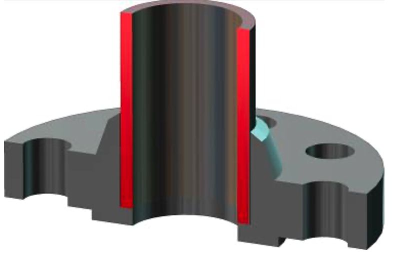
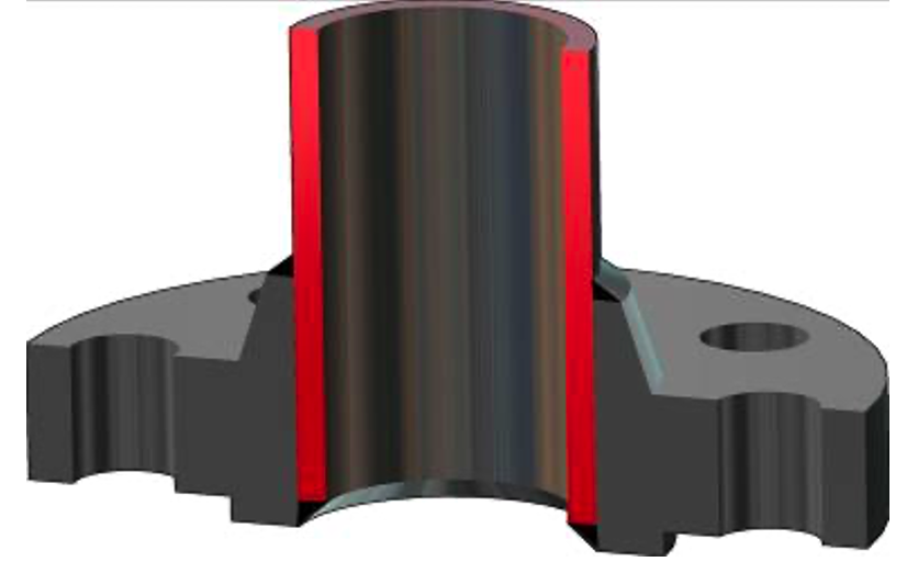
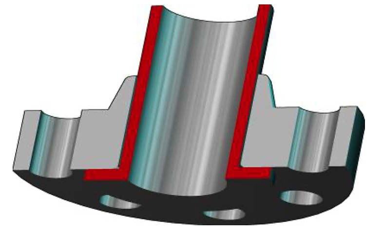
Weld-Neck Flange (WN)
The weld-neck flange is butt-welded to the pipe. This type of flange is typically used on arduous duties involving high pressures and/or hazardous fluids. The butt-weld must be inspected by qualified personnel using radiography or ultrasonics as well as MPI or DPI during the manufacturing process. This provides certification that the welding process that had been carried out was to a high standard and gives confidence in the integrity of the weld.

Socket Weld Flange (SW)
Socket weld flanges are used on hazardous duties involving high pressure, but have limitations, a nominal pipe size (NPS) of 1.1/2 inches.
The pipework is welded to the hub of the socket weld flange. Usual methods of weld inspection such as radiography are not the most practical method on the fillet weld. The weld will normally be inspected using MPI or DPI by qualified personnel.
Slip on Weld Flange (SO)
Used normally on low hazard low pressure services such as fire water, cooling water, etc. The pipe is “double welded” both to the hub and the bore of the flange inspected using Magnetic particle inspection or Dye pen inspection by qualified personnel.
Composite Lap Joint Flange
Comprises of a hub, or “stud end”, welded to the pipe and a backing flange, or lapped flange, which is used to joint the flanges together. These types of flanges are commonly found on CUNIFER and other exotic high alloy pipework. The flange has a raised face and sealing is achieved with a flat gasket such as a Compressed Asbestos Fibre (CAF) or similar gasket type.
ONLY USE COMPRESSED ASBESTOS FIBRE gaskets when specified by the manufacturer and additional PPE may be required when fitting and removing these gasket types. This should be reported as a specialist job undertaken by an approved person.
Swivel Ring Flange
As with the Composite Lap Joint Flange, a hub will be butt-welded to the pipe. The swivel ring sits over the hub which enables the flange to be bolted together. Swivel Ring flanges are commonly found in sub-sea services environments where the swivel ring enables flange alignment. The flange is then sealed using a RTJ metal gasket.

Flange Specification and Identification
4A flange is specified by the following information:
Nominal Pipe Size: Required for all flanges, usually in inches.
Standard: e.g. ANSI B16.5, BS 1560 or API 6A
Type and Facing. For example, whether the flange is “Weld Neck RTJ” or “Socket Weld RF”.
Material: A material specification must be stated and will be as quoted in the piping specification.
Pipe Schedule: Only for WN, socket weld, composite lap joint and swivel ring flanges where the flange bore must match that of the pipe, e.g. sch 40, 80, 120, 160, etc.
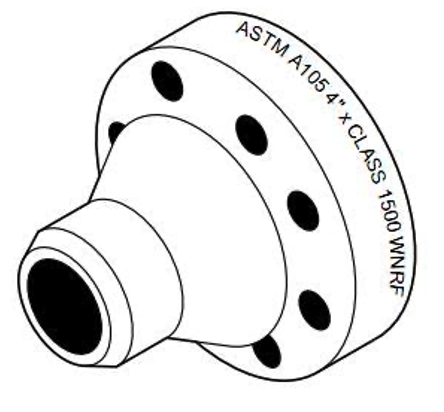
Identification
Flange specification can be found hard stamped on the flange, but in certain cases it may not be easy to read, due to the application of paint or physical corrosion. It is then important to make the identification of the system by referring to the P & ID drawings. As a last resort, we may be required to use measurements and observation, and it may be necessary to attach tags to assist in future identification.
Visual observation: Used to identify the type of joint / flange and the type of gasket (s) used.
Physical Measurement: Measurements can be taken to check the class of the flange in conjunction with known standard flange engineering data.
- Quantity of studbolts.
- Studbolt diameter (Imperial or Metric).
- Bolthole PCD.
- Thickness of flange
NPS and flange pressure class: Some compact flanges use ANSI B16.5 pressure ratings such as class 600, 900, 1500 etc. Other sizes require a design pressure to be specified. Pipe Schedule: Stated in the pipe specification.
Material: The piping specification will detail the material grade of the different components of the compact flange / joints. The manufacturer’s product data sheet should be obtained to determine any abbreviations or material grade that may be stamped on the components.
Also be required for a particular compact flange design. The manufacturer’s product data sheet should be checked for any specifications concerning the different components of the compact flange such as the seal ring, clamps, hubs and even the stud bolts.
Pipe Flanges – Do’s and Don’ts
Do’s
- Visual inspection of both flange / joint mating faces, looking for any damage and cleanliness of the surface faces.
- Remove any physical defects, nicks or burrs. This is extremely important for the back face. This is the spot faces where the nuts come into contact with the flange. Any damage or high spots on this surface will reduce the amount of residual bolt load maintained and be the possible reason for the flanges / joints being unable to maintain the integrity of the system.
- Joints / flanges should be checked for alignment with a straight edge helping to maintain even compression on the flange.
- Check the concentric groove of the surface sealing face of the RF and FF flanges. Any defects will be virtually impossible to seal against and should be reported and rectified.
- RTJ grooves must be clean and maintained, free of any surface corrosion and undamaged.
Don’ts
- When cleaning a flange surface, we should use tools that will cause the least amount of damage to the finish.
- It is recommended we do not use excessive force to assemble flanges which are obviously misaligned as this can induce stresses in the connecting pipe structure, making the sealing of the flanges / joints problematical and unreliable. If you find misalignment or pipeline-in-tension, it is important that we report this situation.
- Never utilise assembled flanges / joints that are manufactured to different standards unless they have been approved?